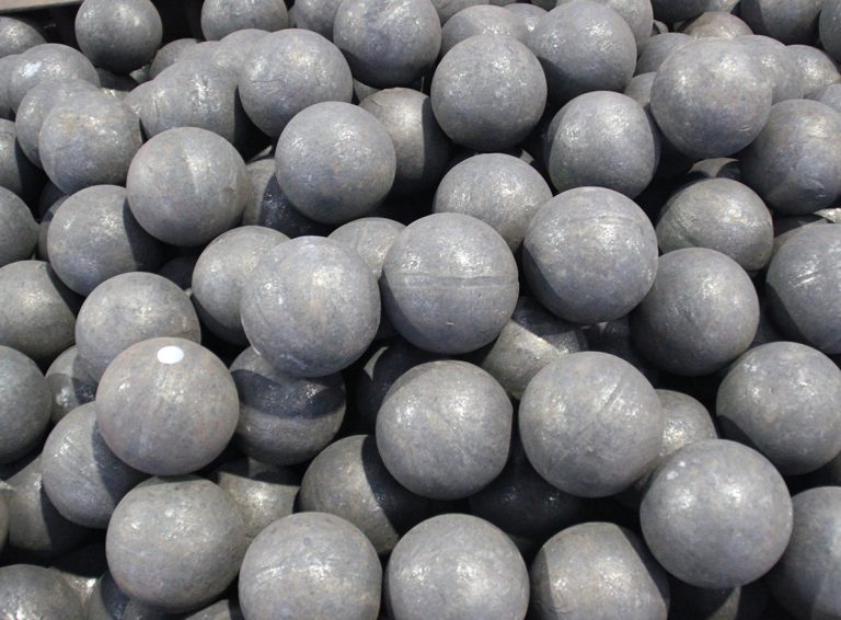
Mill Grinding Balls, Grinding Cylpebs and Grinding Rods
Mill Liner Wear: Five Signs, Causes and Replacement
Mill liner wear is not a single event. It appears as a set of changes across throughput, power draw, product size, shell condition and charge behaviour. By the time a hole is visible, the mill has usually been off its best operating point for weeks. The five signals below can be observed or measured during routine inspections, and together they give a more reliable picture than any one symptom.
Five signs the liner set is worn
- Throughput falls and the power curve changes. A worn lifter profile lifts the charge less effectively, so more power is consumed for the same tonnage, or power drops because the charge is sliding rather than tumbling. A step change in the power trend at constant feed and ball charge is worth investigating.
- Product size becomes coarser. Worn lifting bars reduce the height of the charge and the energy per impact. The product P80 drifts upward, the circulating load rises, and the downstream separation stage may start to see coarser material.
- Slurry leaks at bolts and seams. Gaps at the liner joints allow abrasive slurry to reach the shell. A leak is not only a housekeeping issue: it can indicate bolt elongation, a lost seal, or a crack behind the liner.
- Liner thickness falls to 30–40% of design. This is the most direct measurement of remaining life. The 30–40% threshold is a practical replacement band, not a universal failure point, because the minimum safe thickness depends on the liner profile and the shell support.
- Lifter bars are flat and the charge slips. When the lifting face is worn round, balls slide instead of being lifted. The audible charge changes, power becomes less stable, and wear concentrates at the liner joints and shell fasteners.
Any one sign can have another cause. A coarse product may come from a change in ore or classifier performance; a leak may come from a damaged bolt. Use the signs together with a thickness survey and a power history before ordering a replacement set.
| Mill zone | Dominant wear mechanism | Recommended liner material | Typical life (months) |
|---|---|---|---|
| First chamber (coarse grinding) | High-impact abrasion, gouging, ball impact | Mn13Cr2 or Mn18Cr2 | 12–24 |
| Second chamber (fine grinding) | Sliding abrasion, polishing, low impact | Cr-Mo or high-chromium Cr26 | 18–36 |
| End liners (feed and discharge heads) | Impact, slurry erosion, bolt-hole wear | Mn13Cr2 or Cr-Mo | 12–24 |
| Grate plates and discharge | Abrasion, slot wear, small-ball impact | Cr-Mo or high-chromium Cr26 | 6–12 |
The life ranges are indicative for a well-operated ball mill with a stable feed. Abrasive ore, a high ball charge, or a mill run above its design speed will shorten them. They are not a substitute for measurement on the specific mill.
What causes uneven wear
Feed segregation. A worn feed chute, a misaligned belt, or a damaged feed deflector can send coarse ore to one side of the first chamber. That side then sees higher impact energy and wears faster, while the other side may still have useful thickness. The same pattern can appear when the feed is split between two mills at different rates. Inspect the feed pattern inside the mill during a shutdown and check the chute for a groove or a build-up.
Excessive ball load. A ball charge above the design filling raises contact pressure, power draw and the amount of sliding abrasion at the belly of the mill. The extra grinding capacity is often small compared with the added liner wear and the higher risk of spillage. If the mill is run at a higher ball filling to chase throughput, check whether the power per tonne actually improved before keeping the change.
Material and duty mismatch. Mn13Cr2 depends on work hardening under impact. In a low-impact second chamber it may stay relatively soft and wear by sliding abrasion, while a high-chromium Cr26 liner has excellent abrasion resistance but lower toughness and can crack under repeated heavy-ball impact. Cr-Mo sits between the two. Match the alloy to the dominant mechanism in each zone rather than using one grade for the whole mill.
Insufficient bolt preload. Loose liner bolts allow relative movement between the liner and the shell. The joint opens, slurry enters, and the bolt experiences bending and fatigue instead of pure tension. Tighten to the specified torque in the correct sequence, re-torque after the first heat cycle, and replace bolts that have yielded rather than reusing them.
When to replace the whole set vs part of it
Partial replacement is reasonable when wear is localised, the adjacent liners retain more than about 50% of their design thickness, the shell and bolt holes are sound, and the mill can be stopped again without a production penalty. Replace the whole set when the average thickness is at or below 30–40% of design, when several zones reach the limit together, when cracks or broken liners are present, or when the remaining life is shorter than the next planned shutdown interval. A mixed set with large thickness steps can trap balls and create impact points, so blend the transition instead of leaving a step.
The decision is not only about the number of liners replaced. A partial change means a second shutdown, a second crane lift and a second crew, and it may leave the mill with an unbalanced charge profile. A full change uses more parts but can be the lower-cost option once downtime and lifting are included. The decision should come from the thickness map, not from the calendar alone.
Planning replacement from wear rate
Measure liner thickness at fixed grid points: feed end, mid-mill and discharge end, at four positions around the circumference. Record each reading against its grid position, together with the date, operating hours, tonnes processed, ore type, ball charge and liner part number. Take a baseline measurement at installation, then repeat every 1,000–2,000 operating hours or at each major shutdown. An ultrasonic thickness gauge or a dedicated wear gauge is sufficient; the important part is the same points and the same method each time.
Calculate wear rate as thickness lost divided by tonnes processed, in mm per million tonnes, and as mm per 1,000 operating hours. For illustration, a liner that loses 30 mm over 2.0 Mt has a wear rate of 15 mm/Mt. If the current thickness is 50 mm and the minimum safe thickness is 20 mm, the remaining life is about 2.0 Mt at the same duty. Set the replacement date with a margin for a harder ore or a higher ball charge, and compare the next set’s wear map with the previous one to see whether the material or the profile should change.
To review liner options for a specific mill, see the mill liner range, or send the mill type, chamber dimensions, feed size, ball charge and wear pattern to the contact page. A wear map from the current set is the most useful input for the next specification.